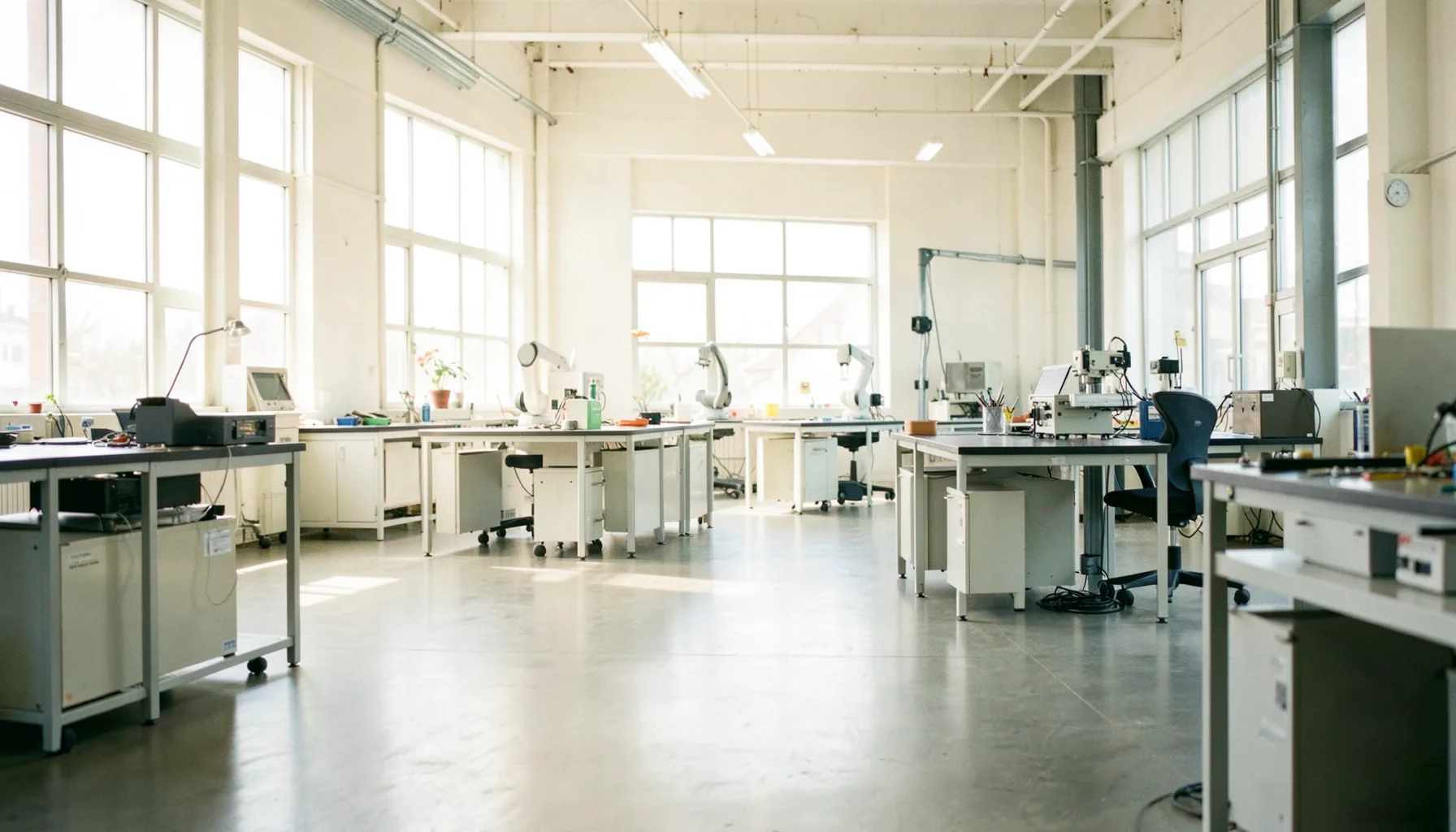
Calculating the Floor Space Required for Your Next Automated Cell
When you decide to introduce an automated cell into a small or medium-sized operation, one of the earliest engineering questions is also one of the most underestimated: how much room does it actually need? Unlike a standalone machine parked against a wall, an automated cell is a coordinated ecosystem of robot, fixtures, conveyors, control cabinets, operator stations and safety infrastructure. Miscalculating the footprint by even a metre or two can ripple through the entire plant, forcing costly re-routing of utilities and traffic.
For Australian manufacturers, particularly those working in tighter inner-Melbourne or western-Sydney factory floors, accurate space planning becomes critical. Lease costs in industrial corridors like Tottenham, Wetherill Park, Dandenong or Hemmant keep climbing, and every square metre wasted is a direct hit to operational economics. A disciplined approach to estimating space from the outset protects both the budget and long-term expansion plans.
Defining the Automated Cell Scope
The first step is a sharp definition of what belongs inside the cell and what sits outside it. An automated cell includes more than the robot itself: the robot base, the work envelope of the arm, the fixture or indexing table, infeed and outfeed conveyors, vision systems, lighting, fencing or light curtains, and the operator interface panel. Anything that touches the work cycle repeatedly should be inside the footprint.
Begin by listing the equipment inside the cell alongside the dimensions supplied by vendors. Add the reach envelope of the robot arm at full extension, plus the swing radius of any rotary indexers. If the cell includes collaborative robots, the stop zones triggered when a person approaches must also be mapped, since these zones expand and contract based on arm speed.
It helps to physically tape out the rough boundary on the floor before installation begins. Many Brisbane-based fabricators and food processors in the Riverina region use this low-tech method to validate vendor drawings against their own reality. A roll of gaffer tape and a walk of the proposed perimeter will surface conflicts with columns, drainage channels, overhead cranes or fire egress paths that rarely appear on CAD exports.
Mapping Robot Reach and Operator Zones
Once the equipment list is firm, the next layer is mapping human interaction zones against the robot's working envelope. Operator stations, HMI screens, load-unload positions, tool change racks and quality inspection points all consume space outside the robot's direct reach but inside the cell's perimeter.
In Australia, where compliance with AS 4024.1 and related safety standards is mandatory, you must also factor in the safety distance calculations derived from the robot's stopping time and the reach of the operator's hand or body. Light curtains and area scanners each create their own geometric footprint, extending the enclosure by 600 mm to 1.2 m on each side depending on configuration.
A common mistake is to assume the robot manufacturer has already optimised the layout. Vendor drawings usually show the smallest theoretical cell that satisfies the cycle time, not the safest or most ergonomic arrangement. Build a paper overlay that places operator reach, sight lines and maintenance access onto the vendor's general arrangement drawing, and the gap between theory and practice becomes visible immediately.
Accounting for Material Flow and Buffer Storage
Material handling is where most space estimates go wrong. A robot cell that performs beautifully in simulation often collapses in reality when parts, totes and finished goods queues encroach on the cell boundary. Buffer capacity between upstream and downstream operations must be quantified in advance, not improvised after commissioning.
Australian lean practitioners often reference the Toyota Production System when sizing buffers, aiming for one-piece flow wherever possible. Real-world constraints such as shift changeovers, varied production schedules and remote workforces in regional South Australia or Western Australia push designers toward small batch buffers of three to ten parts. Each tote or pallet position consumes roughly 0.6 to 1.2 square metres, and these numbers add up quickly across multiple stations.
Don't forget overhead clearance either. Many Australian factories sit inside converted warehouses or older brick buildings with low truss ceilings, particularly in inner-city Adelaide and Fremantle. An overhead-mounted cable carrier, signal tower or EOAT changeover system can demand 1.8 to 2.5 metres of vertical clearance above the robot base, and that volume counts toward the cell's effective envelope even if it does not appear on a floor plan.
Planning Safety Zones and Clearance Margins
Safety shapes the geometry before aesthetic or ergonomic considerations enter the picture. Beyond the basic fenced perimeter, clearance for forklift access, pallet jack movement, maintenance trolleys and emergency egress must be accounted for around all four sides of the cell. Australian workplaces typically apply a minimum 600 mm clearance between the cell fence and any active traffic lane, and 900 mm where pedestrian and forklift paths cross.
Sight lines matter as much as distances. An operator should be able to see the work in progress from a normal standing posture without leaning into the safeguarded space. If the cell contains tall fixtures or inclined conveyors, consider whether cameras or mirrors are needed, and whether those devices alter the layout.
Maintenance access is another hidden cost. Every robot, servo drive, pneumatic valve bank and conveyor motor needs room to be serviced. A practical rule is to draw a 1 m service envelope around every serviceable component and treat any overlap with operator zones as a design compromise. Where overlap is unavoidable, schedule the maintenance during planned outages rather than allowing ad-hoc work inside an active cell, a pattern observed more often in Sydney and Perth operations facing skills shortages.
Validating the Layout with Digital Tools
Before concrete is poured, fencing ordered or utilities routed, run the layout through digital validation tools. A 2D CAD overlay is the entry point, but for cells with significant complexity a 3D simulation in tools such as Visual Components, Siemens Process Simulate or Dassault Delmia is well worth the additional effort. These platforms import your robot model, fixture geometry and human operator model, and reach-conflict analysis flags any pinch points within minutes.
Once the cell is operational, continuous improvement depends on real production data. A practical way to capture this is by introducing a basic production dashboard that tracks cycle times, downtime causes and buffer utilisation against the original space assumption. If the dashboard shows buffers saturating or operators bypassing safety gates, the layout needs revisiting, not the staff.
For sites that lack in-house simulation expertise, the Shinagawa program connects Australian-registered small and medium businesses with vetted integrators who perform feasibility studies at modest co-contribution. This is particularly valuable for manufacturers in regional centres like Geelong, Launceston or Townsville, where local automation talent is harder to source.
Practical Recommendations Before You Finalise Your Layout
- Tape out the cell boundary on the factory floor before signing off vendor drawings; site-specific obstructions rarely make it into the export.
- Add at least 20 percent contingency to your buffer storage footprint, especially where customer demand is seasonal or campaign-driven.
- Confirm compliance with AS 4024.1 and site-specific safety requirements before committing to a fence geometry.
- Reserve a 1 m service envelope around every drive, valve bank and EOAT station to make future maintenance painless rather than punitive.
- Layer a 3D simulation on top of the 2D drawing if your cell combines rotary indexers, vision systems or overhead utilities.
If you are weighing up an investment in automation and want a sanity check on the floor space, layout or subsidy options available through the Shinagawa program, reach out to the team via the website contact form. A short consultation can save months of rework and reposition your project for faster approval and a stronger return on investment.